
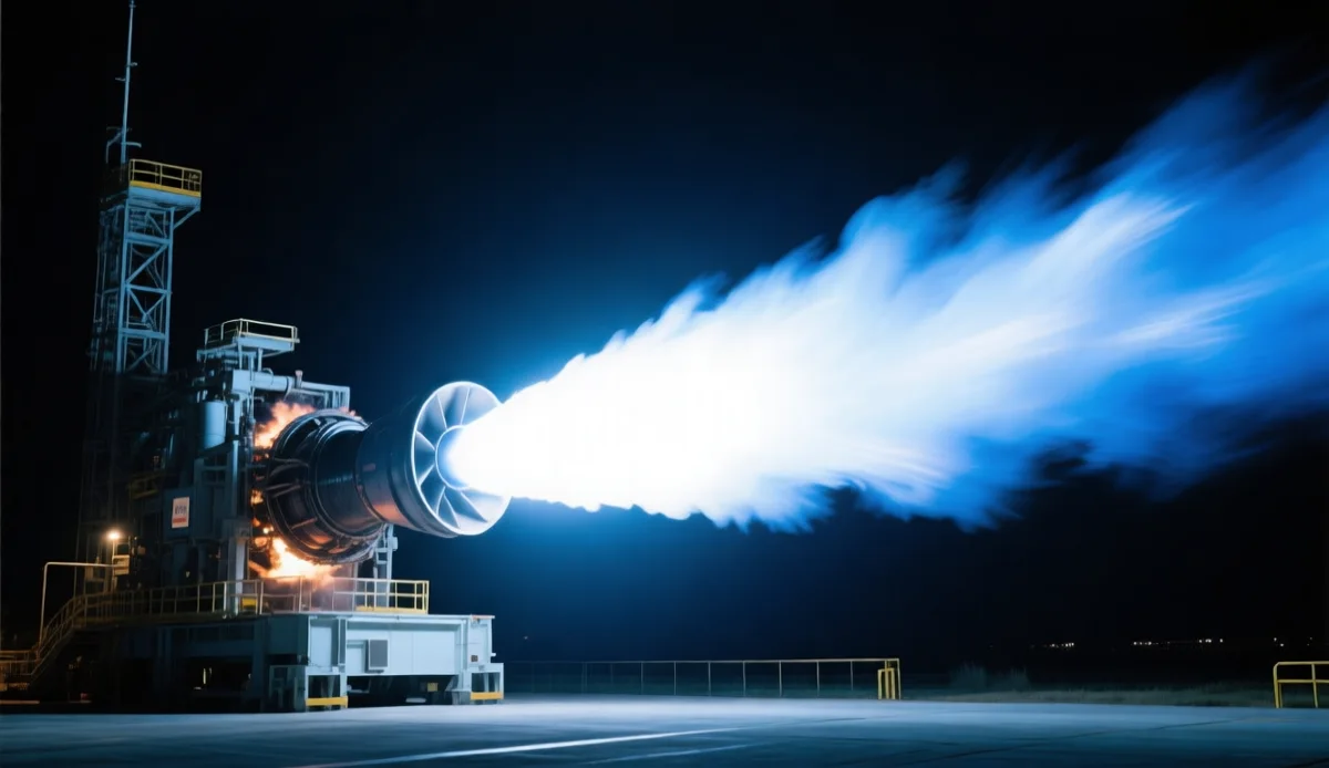
The Raptor 3 engine is the cleanest public case study in designing a product around metal additive manufacturing — not adding AM to a product. SpaceX’s newest full-flow staged-combustion engine lifts thrust to roughly 250 tonnes at sea level (275 in vacuum) while dropping engine mass from about 1,630 kg to 1,525 kg[1] — more push, less metal — and it flew on the twelfth Starship test campaign that transitioned the vehicle to its V3 configuration[2]. Behind those numbers is a decade of subtracting parts: Raptor 2 already collapsed what were once 100+ separate components into heavily consolidated printed assemblies[3], and Raptor 3 pushed the same logic further. This article takes the engine apart conceptually — what AM actually changed in its design, what that teaches any engineering team about consolidation, cooling channels, and iteration speed — and where the same physics shows up outside aerospace.
The Raptor Lineage: A Decade of Subtraction
Rocket engines are traditionally plumbing assemblies. A staged-combustion engine is hundreds of pipes, valves, welds, flanges, and heat shields assembled around the thrust chamber — every joint a leak path, every bracket a mass penalty. The public evolution of the Raptor family reads as a subtraction log:
| Generation | Signature changes | AM’s role |
|---|---|---|
| Raptor 1 (2019 era) | Conventional plumbing-heavy build, external heat shielding | Printed core components already in use (LPBF)[3] |
| Raptor 2 | Parts count cut from 100+ through consolidation; thrust up, mass down | Consolidated assemblies replacing brazed/welded subassemblies[3] |
| Raptor 3 | ~250 tf sea level / ~275 tf vacuum; mass ~1,525 kg (from ~1,630 kg); radically simplified external appearance[1] | Design-native AM: the engine’s shape is what printing allows |
The Raptor 3 mass-thrust inversion is the headline: conventional manufacturing trades one against the other, because stronger, hotter engines need more structure, more cooling jackets, more brackets. Printing breaks the trade by putting the structure inside the cooling architecture instead of bolted around it.
What Additive Actually Changed Inside the Engine
Four mechanisms do the work, and they generalize far beyond rockets:
- Part consolidation. Manifolds, injector bodies, and preburner assemblies that were brazed or flanged collections become single printed bodies. Every deleted joint deletes a leak path, a tolerance stack, an assembly hour, and a failure mode. The economics and the honest limits of this move are the subject of our part-consolidation analysis — Raptor is that article’s argument at 250 tonnes of thrust.
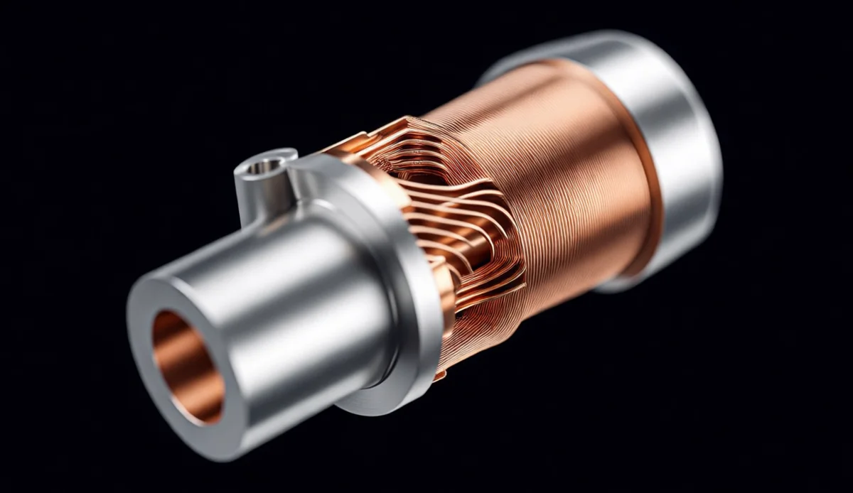
- Internal cooling channels. A rocket thrust chamber is a heat engine wrapped around a cold one: cryogenic methane flows through hundreds of channels milled or formed into the chamber wall before burning (regenerative cooling). Printed chambers put those channels where the heat map wants them — varying pitch and cross-section along the length — instead of where a milling tool can reach. The same microchannel physics is now cooling AI data centers; our copper cold plate article covers the civilian twin of this technology.
- Turbomachinery complexity for free. Full-flow staged combustion runs two preburners and two turbopumps — the densest plumbing in rocketry. Impellers, volutes, and diffusers with organic, bladed geometries are native AM territory: performance shapes that five-axis milling can only approximate in assembled halves.
- Iteration speed. Raptor generations moved faster than any previous engine program because a design change is a CAD change, not a new fixture set. When the test stand is your design review, printing is the only way to afford the review cadence.
The Materials Question: What an Engine Like This Prints In
Public reporting identifies LPBF (laser powder bed fusion) as the core process for Raptor components[3], and the material split follows the physics:
- Copper and copper alloys for chamber liners — nothing else combines ~400 W/m·K conductivity with the strength to survive regenerative cooling cycles. Copper’s reflectivity makes it the hardest common LPBF material, which is exactly why copper AM process maturity is a strategic capability (see the cold plate article above).
- Nickel superalloys — Inconel 718 and 625 class — for preburners, turbopump housings, and hot gas paths, where creep strength at temperature governs. The two alloys’ trade-offs are compared in detail in our Inconel 718 vs 625 guide.
- Stainless for structure. Starship’s airframe itself is rolled and welded stainless, not printed — a useful reminder that AM concentrates where geometry value exceeds its cost premium. The engine prints; the tank does not.
V3 Operations: The Engine in Its Flight Context
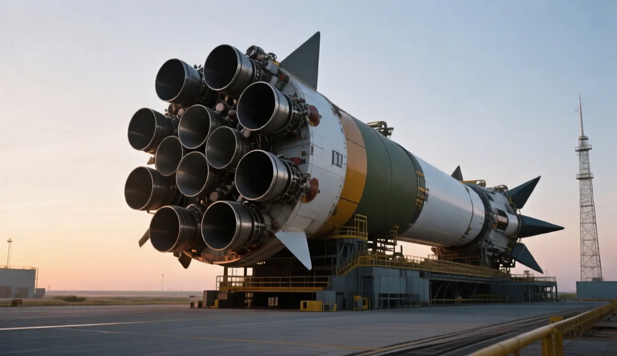
Raptor 3 flies on the Starship V3 vehicle generation, whose twelfth overall flight test campaign moved the stack to the V3 configuration with visible vehicle-level simplifications — grid fins reduced to three, the hot-stage ring eliminated[1] — the same subtraction philosophy at airframe scale[2]. A Super Heavy booster carries 33 Raptor-class engines, so every kilogram saved per engine is multiplied by thirty-three, and every reliability gain per engine compounds across the booster fleet. That multiplication is why engine programs invest in AM process control at production scale: at 33 engines per booster and a fleet flying repeatedly, additive is no longer prototyping — it is the production line.
Production scale also changes the quality question. At fleet quantities, engine performance consistency depends on powder consistency — particle size distribution, sphericity, and oxygen content across batches move fatigue life more than most design changes do. The qualification discipline behind that is detailed in our powder PSD and sphericity guide; it is the unglamorous half of what makes printed flight hardware credible.
This is not a uniquely American story, either. China’s Zhuque-3 program prints its own engine and landing-gear components in titanium — covered in our Zhuque-3 parts analysis — and reusable-rocket programs on both sides of the Pacific now treat metal AM as baseline infrastructure rather than an experiment.
Five Design Lessons for Non-Aerospace Metal AM
| Raptor lesson | General translation | Where it pays |
|---|---|---|
| Delete joints, not just parts | Consolidate around the leak paths and tolerance stacks, not the part count vanity metric | Hydraulics, manifolds, mould tools |
| Put cooling where the heat is | Graded internal channels beat uniform ones; design from the heat map outward | EV battery plates, laser diodes, GPU cold plates |
| Complexity is free, mass is not | Use organic geometry where it removes weight or adds function; keep simple walls simple | Brackets, impellers, lightweighting jobs |
| Material where physics demands | Copper for heat, superalloy for creep, stainless for structure — pay per zone, not per part | Multi-material assemblies, tooling inserts |
| Iterate in metal | Printed test articles compress design cycles; budget for them explicitly | Product development, retrofit engineering |
Every row is a decision a normal engineering team makes on a normal part — which is why the aerospace showcases matter commercially. The processes are the same LPBF machines our process page describes; the difference is only how deliberately the design was written around them.
Common Misconceptions
“Raptor is entirely 3D printed.” No engine is. The printed fraction is concentrated where geometry value lives — chambers, injectors, turbopump components, manifolds[3] — while flanges, fasteners, and ducting remain conventional. “AM-native design” means the architecture assumes printing where it pays.
“Consolidation is always the goal.” Over-consolidation concentrates risk (one bad build loses the whole assembly) and can exceed build envelopes. The Raptor lineage consolidated where joints were the failure mode; our consolidation guide covers the honest math for smaller stakes.
“Only SpaceX-scale budgets justify this.” The mechanisms — deleted joints, graded channels, fast iteration — pay at single-digit batch sizes too, which is where AM tooling economics are actually friendliest. Scale changes the process-control burden, not the design logic.
“Printed engines are fragile prototypes.” The opposite: printed chambers and turbopump components are now flying repeatedly on the world’s most-flown orbital-class hardware. The maturity question is no longer whether AM flight hardware works — it is whether your process control (powder, parameters, inspection) matches the duty.
FAQ
What makes the Raptor 3 engine different from earlier Raptors?
Higher thrust with lower mass: roughly 250 tf at sea level and 275 tf vacuum at about 1,525 kg, down from around 1,630 kg previously. The externally visible simplification reflects deeper part consolidation enabled by additive manufacturing.
How much of a rocket engine can be 3D printed?
The high-value core: thrust chambers with integrated cooling channels, injector assemblies, preburners, turbopump components, and manifolds. Fasteners, flanges, external ducting, and gimbal hardware typically stay conventional. Public reporting confirms LPBF as the core process for Raptor components.
Why does additive manufacturing matter for rocket engines?
Three reasons: it consolidates hundreds of joints into few printed bodies (each joint is a leak path and mass penalty), it enables internal cooling channels that follow the heat map instead of the toolpath, and it collapses design iteration from fixture-cycles to CAD-cycles.
What metals are used in 3D printed rocket engines?
Copper alloys for regeneratively cooled chamber liners, nickel superalloys like Inconel 718 and 625 for hot gas paths and turbopumps, and high-strength steels or titanium for structural components. Material selection follows the thermal and stress map zone by zone.
Is metal AM only for aerospace-scale production?
No. The design mechanisms — consolidation, internal channels, iteration speed — apply to hydraulics manifolds, mould cooling, EV battery plates, and custom machinery at batch sizes of one to hundreds, where AM economics are often better than at aerospace scale.
What is full-flow staged combustion and why does it need AM?
FFSC burns all propellant through two preburners driving two turbopumps before the main chamber — maximum efficiency, maximum plumbing. That density of hot-gas components is exactly what printed consolidation and integrated channels manage; conventional manufacturing hits joint-count and mass walls.
How fast did Raptor iterate compared with traditional engine programs?
Traditional large engine programs run a decade from concept to flight. The Raptor family moved through major generations inside a few years because printed hardware turns each design change into a CAD revision and a build slot instead of new fixtures and tooling — the iteration speed is itself an additive advantage.
Conclusion: The Engine Is the Argument
Raptor 3 is not a 3D-printed engine in the promotional sense — it is an engine whose mass, thrust, and iteration cadence were only reachable by designing around additive from the first sketch. That is the transferable lesson: AM-native design beats AM-enabled design, whether the part produces 250 tonnes of thrust or cools a rack of accelerators. If your assembly has joints that leak, channels that a tool cannot reach, or revision cycles that fixtures slow down, the same subtraction applies. Send the assembly through our RFQ page and we will tell you honestly which parts should consolidate, which should stay conventional — and what the printed ones will cost.
References
- Sina News. “SpaceX 发布星舰 V3 升级” (SpaceX unveils Starship V3 upgrades: Raptor 3 thrust and mass figures). sina.cn, May 13, 2026. Link (accessed September 2, 2026).
- Sina Military. “SpaceX 星舰 Starship 完成第十二次飞行测试:从 V2 过渡到 V3 的关键节点” (Starship completes Flight 12: the V2-to-V3 transition). k.sina.cn, May 2026. Link (accessed September 2, 2026).
- Baidu Baijiahao industry analysis. “万亿市值背后的重要拼图:增材制造在 SpaceX 体系中的真实位置” (Additive manufacturing’s real position in the SpaceX system). Link (accessed September 2, 2026).